Free Modular
Clock Assembly Instructions
See general assembly instructions
Components
Most parts are available on Tayda (cart link, quick-order CSV).
See general components notes for more info about acquiring parts.
| Board | Reference | Part | Value | Source | Comment | |
|---|---|---|---|---|---|---|
| Front | R1-R8 | Resistor | 1kΩ | Tayda | Determines output impedance. Any value is fine. | |
| Front | R9-R16 | Resistor | 5kΩ-10kΩ | Tayda | Determines LED brightness. You may want to use a different value if you have different LEDs. A lower value means less resistance and brighter LEDs | |
| Front | D1-D8 | LED | 3mm | Tayda | Any standard 3mm LED will work here. | |
| Front | SW1 | Rotary Encoder | EC11 series | Tayda, Amazon | ||
| 🔴 | Front | SW2 | Push button | D6R30 F1 LFS | DigiKey | Make sure to line up the flat side of the button with the silkscreen on the PCB. This button could be replaced by a simple “6mm tactile switch” like this with a cap on it, but you may need to adjust the faceplate hole size. |
| 🔴 | Front | Screen | OLED display | SSD1306 SPI | ebay | The underlying display controller is the SSD1306. There are many ebay/amazon sellers that make modules based on it. Make sure to get one that uses the SPI protocol (6 or 7 total pins) instead of the I2C protocol (4 pins). The pins may be labelled differently or be in a different order on different modules. Just connect them to the corresponding holes on the PCB. The module also may or may not contain a 7th RESET pin. Either way should be fine. Different modules may also vary in the layout of their mounting holes. The faceplate is designed for a 23.5mmx24mm bolt pattern, which seems to be common, but it could be easily modified to fit a different screen. |
| Front | J1-J8 | 3.5mm Jack | THONKICONN (a.k.a PJ398SM or PJ301M-12) | Tayda, Thonk | ||
| Front | J9-J11 | Pin headers | 1x4, 1x4, 1x11 | Tayda (Male, Female), Amazon | Solder the two boards directly together using the male headers or make them detachable using a male/female pair. | |
| Back | C1 | Capacitor | - | Optional additional power supply noise filtering capacitor | ||
| Back | C2 | Capacitor | 10uF | Tayda | Power supply noise filtering capacitor | |
| Back | A1 | Arduino Nano | v3.0 | Tayda, ebay | ||
| Back | J9-J11 | Pin headers | 1x4, 1x4, 1x11 | Match corresponding headers on front PCB | ||
| Back | J12 | IDC connector | 2x8 | Tayda | Eurorack power header. Can use two rows of male pin headers or a shrouded connector (recommended). | |
| Back | J13 | - | - | Not used. Expansion points for future features | ||
| 🔴 | Front | - | Mounting bolts | 2 M2x8mm, 2 M2x16mm, 6 nuts | McMaster-Carr | Used to attatch the screen to the faceplate. The two longer bolts can pass through to the PCB using additional nuts to hold everything together more firmly. |
🔴 = Missing from Tayda BOM
Build Guide
Once you have gathered all the components and the PCBs, I recommend starting with the resistors.
Bend the resistor legs back to hold them in place while you solder, then snip off the extra wire.
Repeat for all resistors.
Cut the pin headers to length. Cut between the pins on the male headers but cut over the top of the pins on the female headers.
Stack the boards together and ballance them so that everything sits perpendicular. Solder the joints, then take the boards back apart.
If you prefer, you can solder the boards together permanently using only the male headers. If you do, save this to the very last step so you can still access the solder joints between the boards.
Repeat the same process for attaching the Arduino to the rear board.
Attach the power header and capacitor to the rear board. Make sure to align the notch in the power header with the silkscreen. Looking from the back of the module, the notch should be on the right when the module is upright.
Attach the wires to the screen. If you want, you can use a DuPont connector or a JST XH-2.54 connector to make the screen detachable. Or just solder the wires straight to the screen.
Make sure to trim the tips extra flush so they don’t short out against the faceplate when the screen is attached.
Be careful connecting the screen to the PCB. The pins on the screen may not be in the same order or labelled with the same names as they are on the PCB. This display uses the SPI protocol, which has very inconsistent naming conventions and every order of the display sub-module I get has a slightly different pinout or labels. There should be 6 (or 7) pins on the screen. Connect each one to the matching connection on the module PCB according to the following table:
| PCB marking | Other abbreviations | Function |
|---|---|---|
| GND | 0V, Vss | ground |
| +5V | 5V, PWR, Vcc | power |
| SCK | CLK, SCLK, CK, SLK | serial clock |
| SDA | MOSI, PICO, DATA | serial data |
| RES | RESET | reset (optional*) |
| DC | D/C, MODE, DATA | data/command toggle |
| CS | SS, /SS, /CS | chip select (optional*) |
* The reset and/or CS pins may not exist on the screen sub-module. If not, just leave them unconnected. If they are present then you need to connect them.
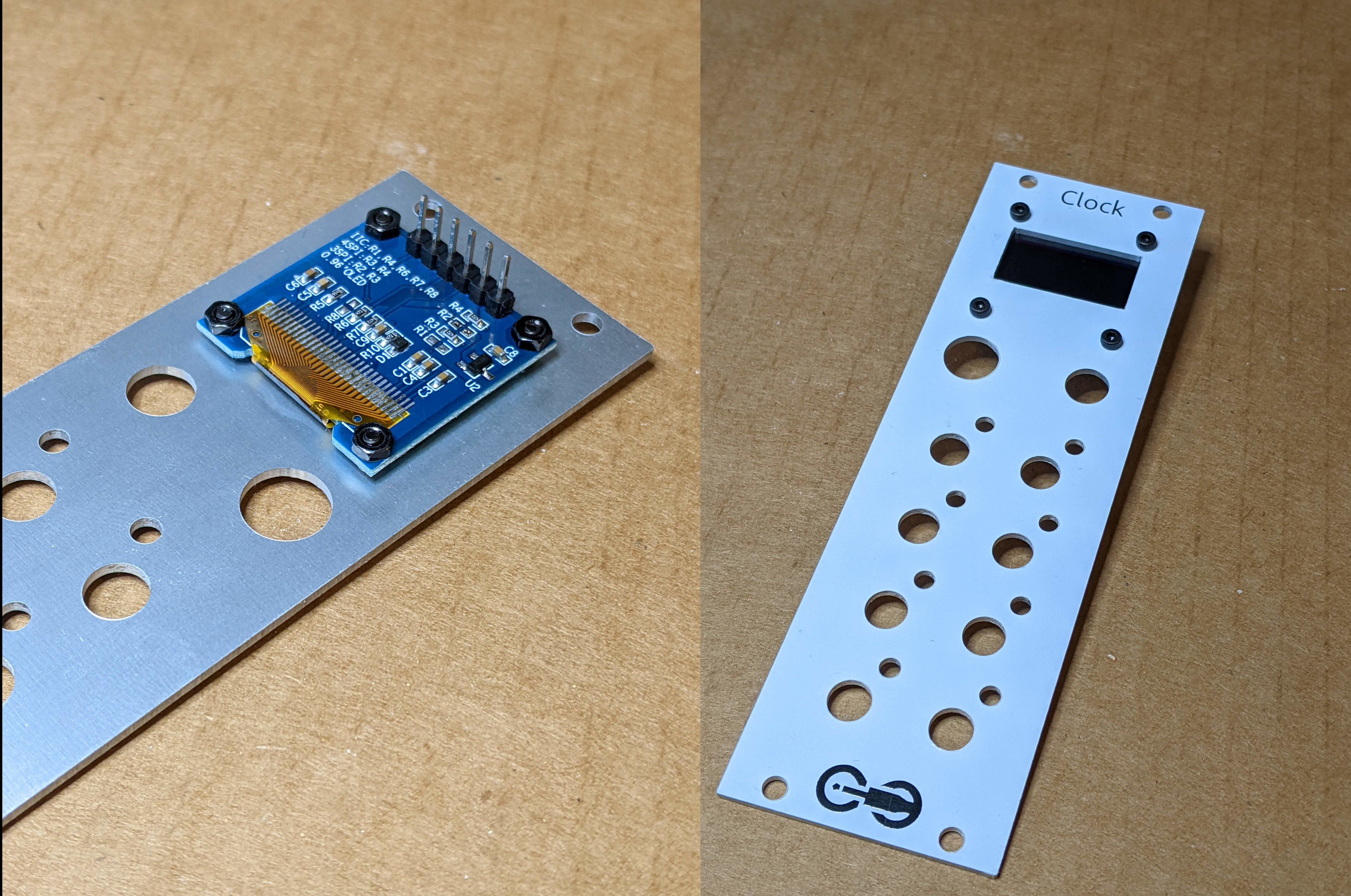
Attach the screen to the faceplate with M2 bolts. Don’t tighten them enough to bend the PCB, just get them gently snug all around.
The connections should be at the top of the module.
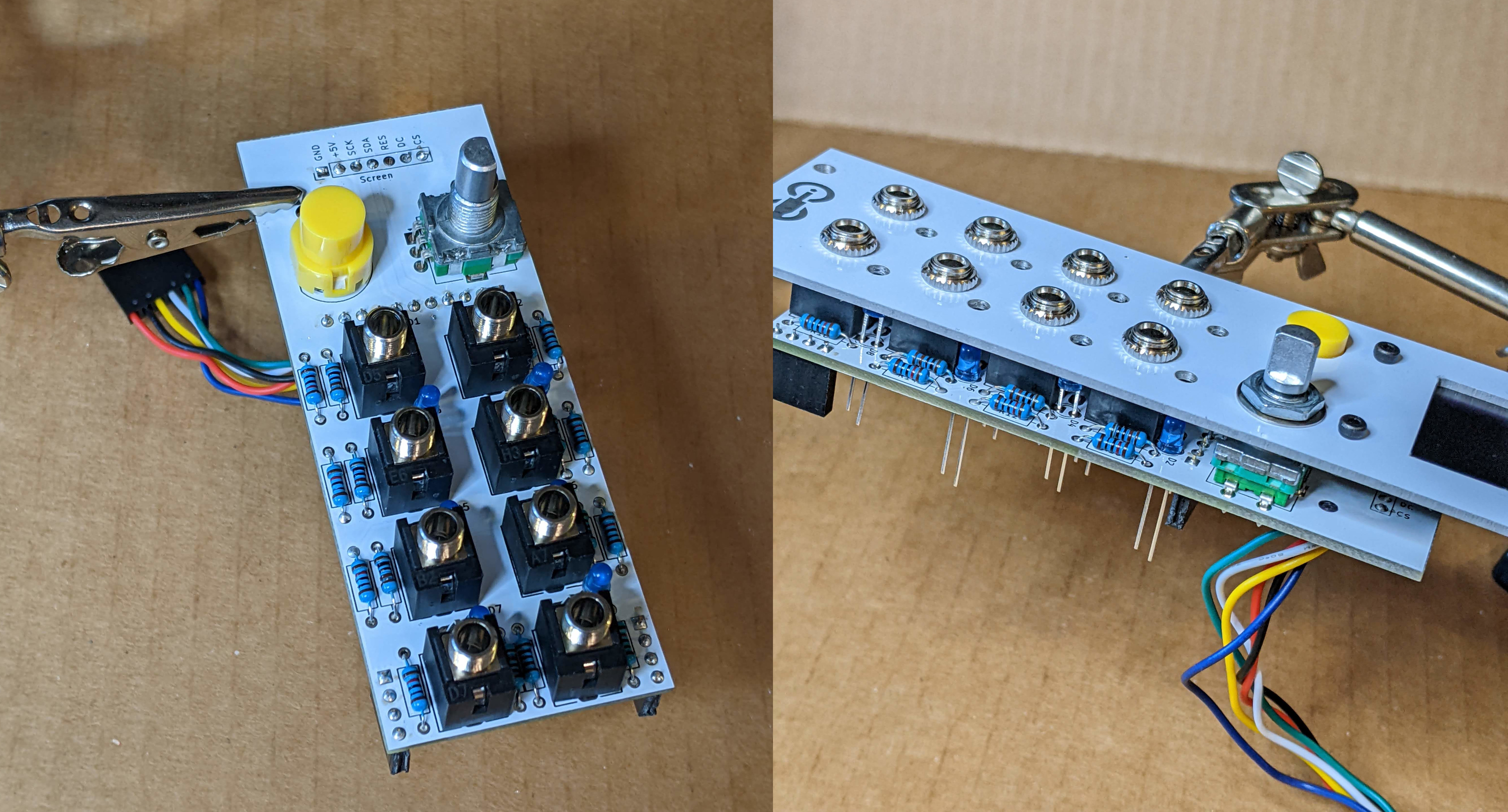
Place all the UI components in the PCB. Make sure to align the flat edge of the button with the silkscreen. The short leg of the LEDs should go in the square holes (toward the bottom of the module).
Add the faceplate before soldering to make sure everything is aligned properly. Screw the jack sockets down tightly. The rotary encoder will not have a surface to tighten the nut against, so don’t screw it on tightly or it will pull the boards out of alignment.
Then flip the whole board over and solder. The button might fall out of place since it isn’t attached. Make sure to hold it flush while you solder.
Push the LEDs through so they stick out the desired amount, then solder them too.
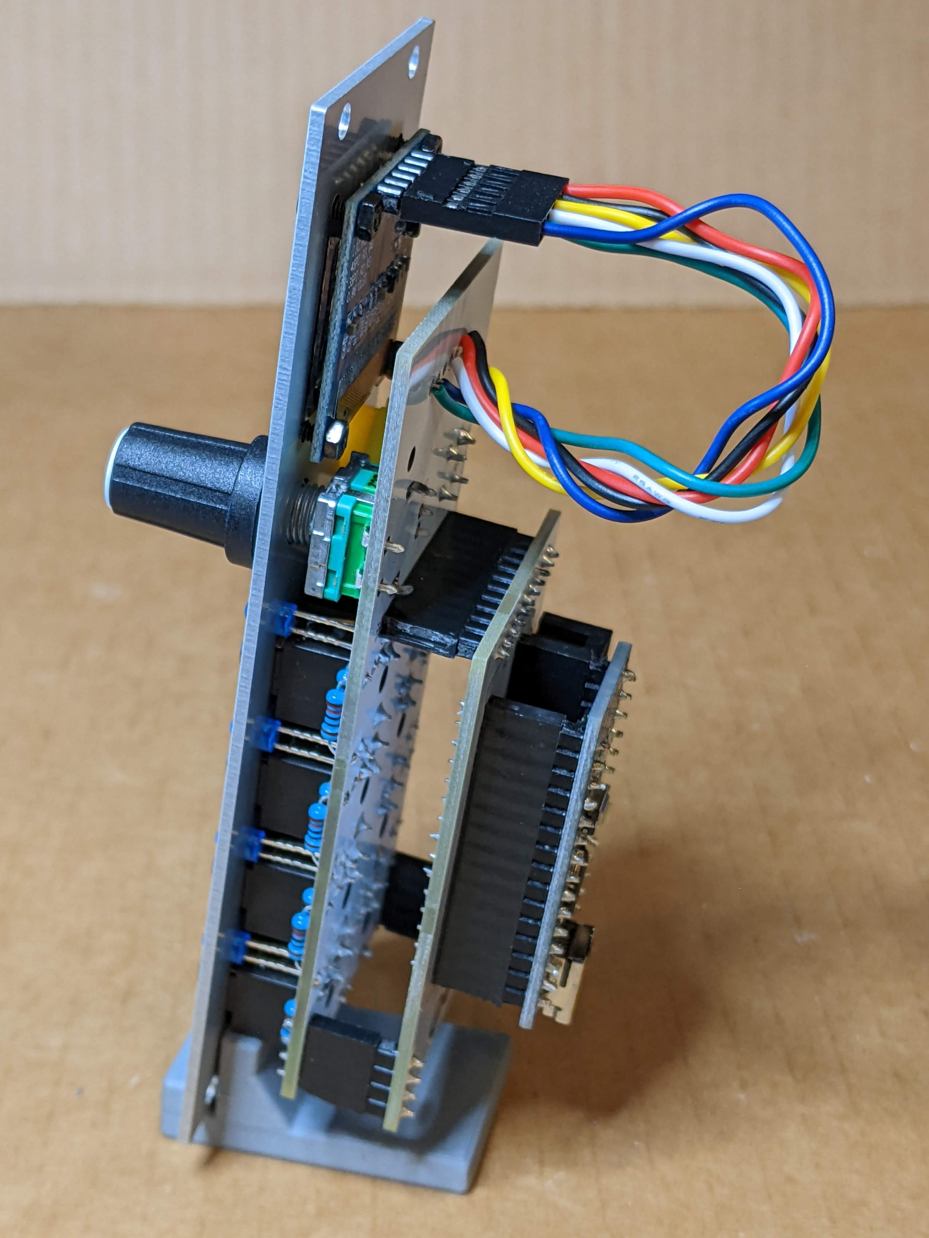
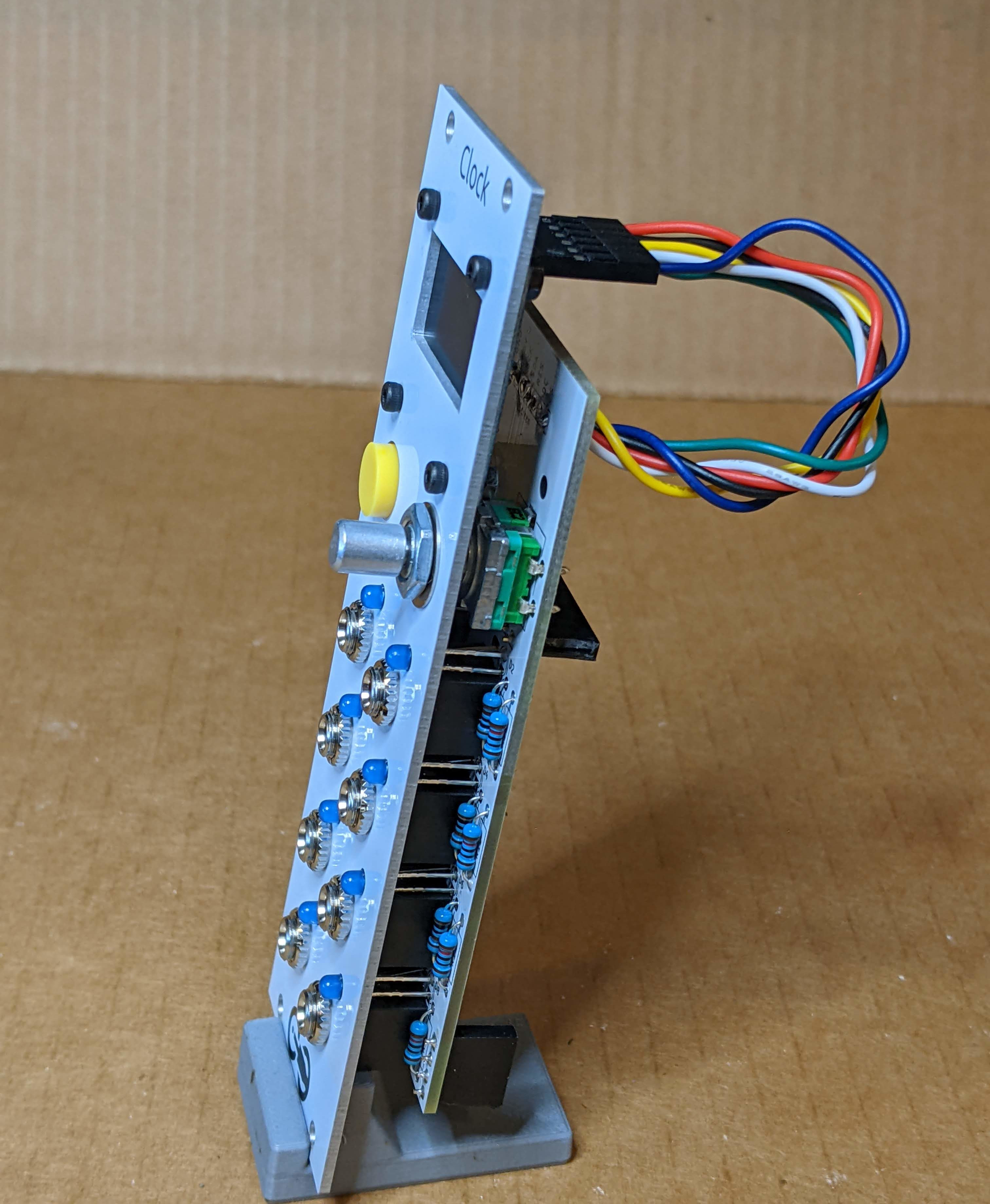
Put the two PCBs back together. Add the knob and the Arduino.
Then flash the bootloader and firmware onto the Arduino, if needed. See the assembly instructions for more details.